
Tel: (480) 219-9007
E-mail: sales@bridgetec.com
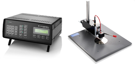
The Multi Height Probe combined with the RM3000+ Test Unit is our most popular combination for use in measuring a wide range of materials and sample sizes.
The Multi Height Probe can be used to measure wafers or larger materials up to 10" x 10", ingots, and materials that are up to 6" inches tall.
See detailsBridge Technology is a manufacturers representative offering equipment for materials research and the semiconductor industry including failure analysis, product engineering, design-debug, test, and production. Select your area of interest by clicking on one of the product choices shown below.
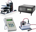
Measure sheet resistance and bulk (volume) resistivity of materials used in the semiconductor industry
This is a complete system for measuring the resistivity, carrier concentration, and mobility of semiconductors.
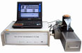
Has automated magnet movement, variable temp capability, and powerful analysis software.

Documents regarding the four point probe technique, correction factors, equations, etc.
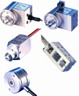
Highest quality four-point probe heads available anywhere in the world.
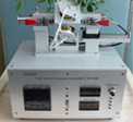
Low cost, easy-to-use, yet powerful Rapid Thermal Processing system which can quickly increase materials to a very high temperature
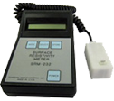
Low cost four point probe for measuring sheet resistance of various thin films, conductive coatings, ITO on glass, etc.